Gear Testing Machines
  • slide-21
  • slide-20
  • slide-19
  • slide-18
  • slide-17
Gear Testing Machines

DuraMax Software CNC Gear Measuring Solutions from Carl Zeiss

Features:
Import and Export from nominal data via various interfaces
Missing teeth
Tooth segments
Nominal points can be masked
Possibility to change the nominal point grid based on the CAD-Model
Measurement flank left and/or right flank
Different tolerances on left and right flank
Single-point or surface tolerances
Calculation of deviations in transversal or normal plane
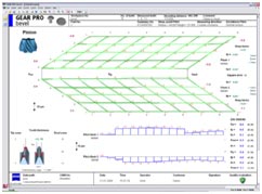
User defined protocol view
Thermo coloured deviations on the CAD-Model
Comparison of two actual files
Axial Fit-In on tooth thickness at CAD-Models (Option)
Evaluation:
Standards
Flank form: Free specification
Pitch
DIN 3965/86
AGMA 2009.98
AGMA 390.03A JIS B1704 / JIS A
Topography
Corner points
Max-/Min- values
nominal/actual comparison each teeth
Global-Format plot with mean values of all teeth
Pressure Angle Error       fa
Spiral Angle Error  fb
Warp factor
Sum of Squared
Pitch/Runout
Accumulated Pitch Deviation               Fp
Single Pitch Deviation                         fp
Spacing Deviation                               fu
Runout                                               Fr
Eccentricity part of Runout                 Frsn (no standardised value)
Tooth Thickness
Output of eccentricity corrected values possible
Tip cone:         angle deviation                - Root cone:          angle deviation
Supported Gear :
worm shafts : 
ZI (evolvent profile)
ZA
ZN
ZK
ZX
Number of teeth
1 – 1000
Module
> 0,5 mm (depends on stylus tip diameter)
Spiral angle
 
<89,5°
Measurement runs
Measurement with rotary table Main axis Z-axis/vertical direction 3- and 4-Axis scanning-mode
Profile
Lead
Pitch/Runout (single flank measurement)
Tip circle diameter
Root circle diameter
Features
Missing teeth
Interrupted lead
Intersection measurement
Different tolerances on left and right flank
Asymmetrical tolerances
Tolerances for mean values
Scanning nominal path or scanning actual path (measurement of big deviations possible)
Calculation of deviations in axial, transversal or normal plane
Topography presentation
Raster lines/horizontal marker lines on printout
Evaluation :
Standards :
DIN 3962
DIN 3974
Free definition of tolerance values
Profile :
Profile Total Deviation               Fα
Profile Form Deviation               ffα
Profile Slope Deviation               fHα
Profile Crowning                        ch
Profile Tip Relief                        ca
Profile Root Relief                      cf
K Diagrams
Lead
Lead Total Deviation                  Fβ
Lead Form Deviation                 ffβ
Lead Slope Deviation                 fHβ
Lead Crowning                          cb
Lead End relief Top                   co
Lead End relief Bottom              cu
K Diagrams
Pitch/Runout
Accumulated Pitch Deviation     Fp
Pitch Span Deviation                 Fpz/8
SinglePitchDeviation                 fp
SpacingDeviation                      fu
Runout                                     Fr
ToothThicknessVariation           Rs
ToothThickness                         Ss
GapWidth                                 Es
Dimensionover1-ball                  MrK
Dimension over 2-balls              MdK
Dimension over 2-pins               MdR
Spanwidth over k teeth              Wk
Lead Height
Output of eccentricity corrected values possible
Tip circle diameter :            da
Root circle diameter :         df
Gear Testing Machines