|
Spur Gears, Bevel Gears, Worms.
GEAR PRO – CAD-based gear wheel software |
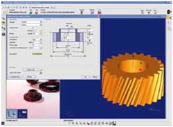
Used together with CALYPSO, the GEAR PRO line enables you to inspect spur gears, bevel gears and worms. GEAR PRO generates a CAD model of the gearing from the geometry definition. The graphic display allow separators to quickly and visually check their input values. A standard measurement can be performed immediately based on the definition of the geometry. |
 |
| |
All GEAR PRO programs feature the same easy-to-use interface. Gear measurements can be started either automatically from a CALYPSO measurement plan or manually in the corresponding GEAR PRO program.
The analytical 3D gear tooth model and the graphic-supported input windows make measuring with GEAR PRO highly effective. The software enables measurements with or without a rotary table. Several measuring runs can be defined per measurement plan and features can be turned on and off. An optional qs-STAT interface is available for statistical evaluation. |
|
| |
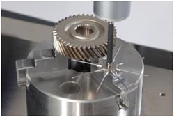
| GEAR PRO involute was specially developed to Measure spur gears. |
• |
Straight or slanted-tooth spur gears |
• |
Conically corrected gears |
• |
Splines |
|
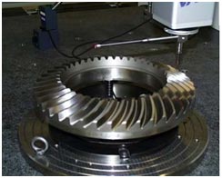
| GEAR PRO bevel measures and evaluates bevel gears. Nominal values can either be imported via the CAD interface (Gleason, Klinglenberg, Daimler-ZAFE, CCDS) or generated by digitizing a master gear. |
| GEAR PRO worm is used to measure worms. GEAR PRO worm takes into account the different geometries from ZA, ZI, ZK and ZN worms |
| |
| GEAR PRO Involute- Product specification |
| Supported Gear: |
| 1. |
Cylindrical Gear: |
| |
• |
With involute profile |
| |
• |
External & Internal Gear |
| |
• |
Spur & Helical Gear |
| |
• |
Splines |
| 2. |
No Of teeth : |
| |
• |
1-1000 |
| 3. |
Module : |
| |
• |
> 0.5 (depends on stylus tip diameter) |
| 4. |
Helix Angle : |
| |
• |
< 89.9° |
|
 |
|
| Measurement Run : |
• |
Profile |
• |
Lead |
• |
Pitch /Runout (single Flank/Double Flank , Self-centring) |
• |
Tip & Root Circle Diameter |
| Features : |
• |
Import & Export from nominal data from via GDE-interface |
• |
Different geometry data on left & right flank |
• |
Missing teeth |
• |
Interrupted lead |
• |
Intersection Measurement |
• |
Element Selection left and or right flank |
• |
Different tolerance on left and right flank |
• |
Asymmetrical Tolerance |
• |
Tolerance for mean value |
• |
Scanning Nominal path or scanning actual path (Measurement on Big deviation possible) |
• |
Calculation of deviation in axil Transversal Or Nominal Plane |
• |
Topography presentation. |
• |
Tooth gap measurement |
• |
Automatic stylus system selection at measurement |
• |
Raster line /horizontal marker line on print out |
|
| Evaluation : |
| Standards : |
• |
DIN 5480 |
• |
ISO 1328 |
• |
AGMA 2000-A88 |
• |
ANSI B92.1 |
• |
JIS B1702 |
• |
Free definition of tolerance values |
• |
Customer specific standards (Scania, Volvo, ZF, Renault) |
| Profile : |
| • |
Profile Total Deviation Fα |
| • |
Profile Form Deviation ffα |
| • |
Profile Slope Deviation fHα |
| • |
Profile Crowning ch |
| • |
Profile Tip Relief ca |
| • |
Profile Root Relief cf |
| • |
K Diagrams |
| Lead |
| • |
Lead Total Deviation Fβ |
| • |
Lead Form Deviation ffβ |
| • |
Lead Slope Deviation fHβ |
| • |
Lead Crowning cb |
| • |
Lead End relief Top co |
| • |
Lead End relief Bottom cu |
| • |
K Diagrams |
| Pitch/Runout |
| • |
Accumulated Pitch Deviation Fp |
| • |
Pitch Span Deviation Fpz/8 |
| • |
SinglePitchDeviation fp |
| • |
SpacingDeviation fu |
| • |
Runout Fr |
| • |
ToothThicknessVariation Rs |
| • |
ToothThickness Ss |
| • |
GapWidth Es |
| • |
Dimensionover1-ball MrK |
| • |
Dimension over 2-balls MdK |
| • |
Dimension over 2-pins MdR |
| • |
Spanwidth over k teeth Wk |
| • |
Lead Height |
| • |
Output of eccentricity corrected values possible |
| Tip circle diameter : da |
| Root circle diameter : df |
|
| Supported Gear : |
| Bevel gears : |
| Pinion |
| Worm pinion (high reduction pinion) |
| Ring gear |
| Dies |
| Spur and spiral gearing |
| Number of teeth |
| 1 – 1000 |
| Module |
| > 0,5 mm (depends on stylus tip diameter) |
| Spiral angle |
| < 80° |
|
 |
|
| Measurement runs: |
| Measurement with rotary table Main axis Z-axis (vertical direction) |
| Measurement without rotary table (NSP for ring gears and spur pinions) |
| Feed-In direction Z-axis (ring gear) |
| Feed-In direction X-axis (pinion) |
| Topography |
| Pitch/Runout (single flank measurement) |
| Tip cone |
| Root cone |
| Flank form nominal points |
| Nominal data import via various interfaces |
| Nominal data generation using a master gear (creation up to 3 sub grids possible) |
| Nominal data generation via CAD-Model (SAT, STEP, IGES) |
| Interfaces (optional): |
| Name of interface |
Actual data export for correction data calculation |
Standard (ASCII/Bevel Unix) |
- |
RAM-300-Data (CMS) |
- |
Gleason (GAGE4Win) |
Manual/Automatic |
Klinglenberg (KIMOS) |
Manual/Automatic |
Oerlikon (CDS) |
Manual |
DaimlerChrysler (ZAFE) |
Manual/Automatic |
|
|


