|
 |
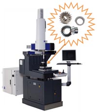
CNC Gear Measuring Solutions from Carl Zeiss |
Reliable, high-quality measuring technology consists primarily of the Gear measuring machine, well-engineered software and customer service and support. At Carl Zeiss, these elements interact in perfect harmony.
We are your one-stop provider of GEAR metrology solutions. |
• |
Technology from Carl Zeiss |
• |
3D Scanning VAST Probe Head |
• |
Robust Design |
• |
Small Foot Print |
|
|
|
| Machine Technology |
• |
Reliable drive technology |
• |
Completely covered guide ways |
• |
Integrated damping system |
• |
Compensation of guide way errors (CAA corrected) |
| Technology from Carl Zeiss, The Market Leader |
• |
C99 controller technology |
• |
VAST XXT scanning sensor |
• |
GEAR PRO &CALYPSOmeasuring software |
• |
Compensation of guide way errors (CAA corrected) |
• |
No special installation or power requirements |
|
 |
| Sensor Systems |
• |
VAST XXT scanning sensor from the technology leader |
• |
Probe for single-point measuring and scanning |
• |
Stylus receptacle for CNC-guided stylus change |
• |
Adapter plate with 25 mm diameter for optimal reproducibility |
|
|
|
| Range of Application |
DuraMax RT |
|
| No. of Axes |
4 |
|
| Module Range |
> 0.5 |
mm |
| Maximum Outside Diameter Spur Gear |
450 |
mm |
| Maximum Outside Diameter Helical Gear |
450 |
mm |
| Measurable Gear Face Width |
400 |
mm |
| Maximum Helix Angle |
90 |
° |
| Axes Travel (X x Y x Z) |
500 x 500 x 380 |
mm |
| Environmental Requirements |
20 to 30 |
°C |
|
|
| GEAR PRO Software |
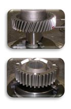
GEAR PRO INVOLUTE : For Spur & Helical Gears
|
 |
FEATURES :
Profile, Lead, Pitch & Runout (Single Flank / Double Flank / Self Centering method)
Tooth Thickness Variation, Tooth Thickness, Gap Width, and Dimension over 1-ball /2-balls,Dimension over 2-pins, Span width over k teeth, Output of eccentricity corrected values, Measurement of Tip & Root Diameter
Missing Teeth, Tooth Segments, Interrupted Lead
Calculation of deviation in Axial, Transverse or Normal Plane
Topography presentation, Tooth / Gap Measurement
Raster Lines or Horizontal marker lines
Evaluation according to standards: DIN 3962, DIN 5480, ISO 1328, AGMA 2000-A88, ANSI B92.1, JIS B1702, customer specific standards (Scania, Volvo, ZF, Renault) |
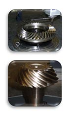
GEAR PRO BEVEL: For Bevel Gears (Pinions, Worm Pinions, Ring Gear, Diesand Spur&Spiral Gearing)
|
 |
FEATURES :
Feed in X / Z Direction for Pinion & Ring Gear
Topography: Corner points, Max-/Min- values, nominal/actual comparison each teeth,
Global-Format plot with mean values of all teeth, Pressure Angle Error, Spiral Angle Error, Warp factor, Sum of Squared, Pitch & Runout, Root Cone, Tip Cone
Missing Teeth, Tooth Segments
Thermo coloured deviations on the CAD-Model, Comparison of two actual files
Nominal data import via various interfaces
Nominal data generation using a master gear
Nominal data generation via CAD-Model (SAT, STEP, IGES)
Standards: DIN 3965/86, AGMA 2009.98, AGMA 390.03A, JIS B1704 / JIS A
Interfaces: Standard (ASCII/Bevel Unix), RAM-300-Data (CMS), Gleason (GAGE4Win), Klingelnberg (KIMOS), Oerlikon (CDS), DaimlerChrysler (ZAFE) |
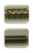
GEAR PRO WORMS:For Cylindrical Worms (ZI (Evolvent profile), ZA, ZN, ZK, ZX)
|
 |
FEATURES :
Profile, Lead, Pitch/Runout (single flank measurement), Tip circle, Root circle
Tooth Thickness Variation, Tooth Thickness, Gap Width, Dimension over 1-ball /2-balls,Dimension over 2-pins, Span width over k teeth, Output of eccentricity corrected values, Lead Height
Missing teeth, Interrupted lead, Intersection measurement
Element selection left and/or right flank, Different tolerances on left and right flank
Asymmetrical tolerances, Tolerances for mean values
Scanning nominal path or scanning actual path (measurement of big deviations possible), Calculation of deviations in axial, transversal or normal plane
Topography presentation, Raster lines/horizontal marker lines on printout
Standards: DIN 3962, DIN 3974, Free definition of tolerance values. |
|
 |
 |
 |
|
|


